Torqbyte Tech Blog

Updating CM5-LTS Firmware for Use With TorqTune2

This guide will explain how to update the CM5-LTS firmware so the unit can be used with the latest TorqTune2 software.

Note: This firmware update can only be performed on current CM5-LTS units with rectangular LEDs. It is not compatible with older CM5-LT units with round LEDs. Some early LTS units were branded LT, so always verify the shape of the LEDs to determine if the unit in question is an LT or an LTS regardless of what is stated on the enclosure.

CM5-LT vs CM5-LTS Side-by-Side Comparison 

Step 1: Ensure you are updating the latest WMI controller version CM5-LTS (with rectangular LEDs) and not an older CM5-LT (with round LEDs). Note: Once this update is performed, there is no way to go back to the old firmware / TorqTune without sending the unit back to us.

Step 2: Go to our Support Page (login may be required)

Torqbyte Support Page

Step 3: Download, Unzip and Install TorqTune2, but don't run it. Note: TorqTune2 only works on Windows machines.

TorqTune2

Step 4: Ensure that TorqTune2 is closed. Download and Unzip the CM5-LTS authentication utility.

CM5-LTS Auth Utility

Step 5: Extract the Authentication Utility to your hard drive. Note: Don't just run it from the temporary browser downloads folder.

Step 6: Connect the controller to the computer using the provided USB cable. Navigate to the folder where the utility was extracted. Right click on the [CM5-LTS_Authenticate] executable and click [Run as administrator].

Run the Authentication Utility

Step 7: A window like this should appear. Please take a screenshot of this window or copy/paste its contents and email this to us at support AT torqbyte DOT com (obviously change AT to @ and DOT to a period). Close the Authentication Utility.

Authentication Utility Output

Step 8: We will email back a ZIP file with a custom CM5-LTS firmware for your controller. It may take up to 48hrs for us to respond. If you don't receive a reply in that time please check your trash or spam folder to make sure our email didn't get filtered out by your email program. Unzip the attachment and save it to your hard drive. Note: the firmware is locked to the specific controller. If you load the provided firmware onto a different controller that controller will become unusable.

Step 9: Connect the CM5-LTS to the computer or laptop with TorqTune2 installed using the provided USB cable. Wait for Windows device plugged in sound or watch the LINK LED on the CM5-LTS to ensure it's ON solid. You can do this at your desk with the unit out of the car since it will be powered from the USB port.

Step 10: Launch TorqTune2.

Step 11: Click the [FW Update] button.

TT2 FW Update

Step 12: Click the [Browse] button and navigate to the folder on your hard drive where the file we emailed you was extracted to. Click OK to select the file and click the [Update Firmware] button. Wait for the 2 green progress bars at the bottom to complete.

TT2 FW Update 2

Step 13: At this point you will notice the unit's top LED flashing indicating it has the new firmware, but still needs to be configured. To do this, start by clicking the [New] button.

New Config File

Step 14: This will bring up a prompt asking you to input some basic parameters related to your setup, which sets up the rest of the duty tables, etc. Note: You can just leave these values "as-is" at their default values for the purposes of setting up the unit, but if you want to change any of these later on you will have to create a brand new configuration file from scratch, by clicking the [New] button again. Once you are done editing these fields, click [OK] at the bottom.

TT2 New File Prompt

Step 15: Click the [Write] button to apply this configuration to the unit. With this the top LED should stop flashing and should be solid ON indicating the CM5-LTS has been properly configured.

TT2 Write Configuration

Step 16: Each time you want to make configuration changes (assuming the unit is connected via USB and TT2 is running), you should start by clicking [Read] to first import the controller's configuration into TorqTune2. Next step should be to click [SaveAs] and give this configuration a unique name with a date/time so you can always go back to it if the changes you are about to make don't work out. Now you can make changes and periodically click [Write] to apply them to the unit.

Posted by Torq Byter_ on 16 August, 2022 Read more →

Determining TorqTune2 MAP Sensor Values

CM5-LTS is able to obtain boost readings from any analog 0-5V Manifold Absolute Pressure (MAP) sensor, but it requires the user to provide a few senor-specific MAP Calibration parameters (Slope, Intercept, Atmosphere and Deadband) in order to accurately convert the sensor voltage to boost pressure.

Torqtune2 MAP Settings

Torqbyte frequently tests popular MAP sensors and publishes TorqTune parameters for those sensor on its website. In instances where the customer wishes to use a MAP sensor we have not yet tested, this blog post will outline the procedure that a customer can follow in order to determine the required parameters themselves.

Before we go further it should be noted that there are two common ways to measure pressure. Absolute pressure reading includes the current atmospheric pressure. Gauge pressure reading does not. So if the pressure was measured at seal level with an Absolute pressure sensor the reading would be 14.696 psi (1,013.25 mbar). If it was measured with a Gauge pressure sensor the reading would be 0.0 PSI (0.0 mbar). The reason this is important to note is that the customer needs to be aware which of the two methods they are using to make the pressure measurements to be used in the procedure described below.

If you have a datasheet for the sensor in question that provides a Voltage vs. Pressure graph for it, you can skip to the example below. Otherwise, read on for a procedure that can be followed to work out the required parameters for any MAP sensor even if if its Voltage vs. Pressure relationship is not known.

Required Equipment and Information

1. A way to measure the sensor voltage. Here you can use a digital multimeter or you can use TorqTune2 Live View Tab. On that tab click [Show advanced data] and observe on the Pressure (V) field just below the [Show advanced data] button.

Advanced Data

For this procedure the sensor has to be powered. If using the OEM sensor the engine computer must be powered on. If using the CM5 to power the sensor the unit must have battery power and must have its Orange wire connected to +12Vdc (do not use just the USB power from a connected laptop)

2. A way to pressurize the manifold or at least the sensor by itself. DO NOT use compressed air unless you have an in-line regulator that can limit the pressure that gets applied to the sensor. In most cases a hand pump or a large syringe works best. DO NOT do this with the engine cranking ot running since the engine will be creating a vacuum.

3. A way to independently measure the pressure being applied to the sensor. This could be a standalone electronic or mechanical pressure gauge or a pod-mounted boost gauge or tuning / OBD monitor software. Whatever the method chosen you will need to be sure you know if what you are looking at is showing you Absolute or Gauge pressure readings. You should also be reasonably sure that whatever is used here is as accurate as possible.

4. Current Atmospheric pressure from your favorite weather channel or weather app. This needs to be in millibar (mbar) !!! If it's provided in other units you need to convert it to mbar before doing anything else. 

5. A way to relate readings in No.1 and No.3 at the same instant in time. We're trying to determine the sensor voltage at a given pressure. If the way of pressurizing the senor is static (i.e. you can apply some pressure and have it hold) then you can just write down the voltage and write down the pressure. If the applied pressure is rapidly changing you may need to film whatever is measuring the voltage and whatever is measuring pressure at the same time and just pause the video at certain points to capture voltage and pressure readings side by side.

Processing the Collected Data

Step 1: Work out the current Atmospheric Pressure in mbar.

Step 2: Select one "low" pressure/voltage reading and one "high" pressure/voltage reading. Ideally, these should be as far apart as possible while still being within the expected boost range of the vehicle in question.

Step 3: If the pressure measurements were made with an Absolute sensor you already have the data you need. If they were made with a Gauge sensor (like a pod-mounted boost gauge) you need to first convert those readings into mbar then add the Atmospheric Pressure value from Step 1 to each of those readings.

Step 4: Open MS Excel and enter the data collected as follows:
Low Voltage into cell A1, Low Pressure (in mbar) into Cell B1
High Voltage" into cell A2, High Pressure (in mbar) into Cell B2

Click into another cell where you want the TorqTune2 Slope value to be calculated and enter the following formula:

=ROUND(SLOPE((B1:B2)*100,A1:A2),0)

Click into another cell where you want the TorqTune2 Intercept value to be calculated and enter the following formula:

=ABS((ROUND(INTERCEPT((B1:B2)*100,A1:A2),0))-101325)

TorqTune2 Atmosphere field should be set to the value in Step 1 multiplied by 100.

Lastly, the Deadband value is the minimum amount of boost (in psi) the engine must generate before the pump tables are allowed to activate. This is an important safety feature designed to prevent pump activation when the engine is off or not making boost. Default value is 3 psi and we recommend you keep it at that.

Example

In this example we'll work out the TorqTune 2 parameters for the 100 psi MAP Sensor we offer as an option with the CM5-LTS kits.

Honeywell 100PSI MAP

The OEM Part No. of this sensor is PX3AN2BS100PAAAX

If we look up the datasheet for this sensor we can see it includes a graph of Voltage vs. Pressure

Honeywell 100 psi MAP Voltage Pressure

We can see that at 0 psi (absolute) this sensor outputs 0.5V and that at 100 psi (absolute) it outputs 4.5V. Converting psi to mbar we get

0.5V @ 0.0 mbar
4.5V @ 6894.76 mbar

We also note the current atmospheric pressure in our area is 14.7 psi (1013.25 mbar)

Now we go over to Excel and enter the following into cells A1, A2, B1 and B2

Excel Data

Using the two formulas above we get Excel to calculate the Slope and Intercept Values for TorqTune2

Excel Calculation

That gives us our Slope and Intercept Value.

The TorqTune 2 Atmosphere value is just the atmospheric pressure in our area (in mbar) multipled by 100, which in our example is 1013.25 x 100 = 101325

We also decide to leave the deadband at the default value of 3PSI and up with the following TorqTune2 values for this particular MAP sensor:

Updated TorqTune2 MAP Settings

Finally, click Write to apply these values to the unit. Then click Read, File->SaveAs to save the unit's new configuration so you can go back to it in the future, if required.

Posted by Torq Byter_ on 29 October, 2021 Read more →

Using the Factory BMW T/MAP Sensors with the CM5-LTS

In most BMW applications with a CM5-LTS WMI controller, it is preferred to obtain boost readings by "teeing" into the factory TMAP sensor wiring. Below is the information on how to do this for several popular BMW TMAPs we have tested.

The numbers below are derived from a sample of one sensor each that we have tested. The numbers below may differ for individual sensors in different cars.

OEM Part No. 13627843531
Pressure Rating: 3.5Bar (Absolute) => 2.5Bar / 36PSI (Boost)

TorqTune Settings:

Slope: 19.533
Intercept: 247.991
Atmosphere: 251

.:: NEW ::. TorqTune2 Settings:

Slope: 72224
Intercept: 86202
Atmosphere: 101325

Wire Connections:

Pinout for BMW 13627843531 13627551429 13627585493

//***************************************************

OEM Part No. 13627551429 (Old) / 13627585493 (New)
Pressure Rating: 2.5Bar (Absolute) => 1.5Bar / 21PSI (Boost)

TorqTune Settings:

Slope: 25.556
Intercept: 403.854
Atmosphere: 407

.:: NEW ::. TorqTune2 Settings:

Slope: 55684
Intercept: 108160
Atmosphere: 101325

Wire Connections:

Pinout for BMW 13627843531 13627551429 13627585493

//***************************************************

OEM Part No. 13628637900
Pressure Rating: 2.5Bar (Absolute) => 1.5Bar / 21PSI (Boost)

TorqTune Settings:

Slope: 24.342
Intercept: 396.193
Atmosphere: 398

.:: NEW ::. TorqTune2 Settings:

Slope: 58260
Intercept: 110796
Atmosphere: 101325

Wire Connections:

Pinout for BMW 13628637900

//***************************************************

OEM Part No. 13628637896
Pressure Rating: 4.0Bar (Absolute) => 3.0Bar / 45PSI (Boost)

TorqTune Settings:

Slope: 14.960
Intercept: 262.466
Atmosphere: 225

.:: NEW ::. TorqTune2 Settings:

Slope: 87597
Intercept: 94651
Atmosphere: 101325

Wire Connections:

Pinout BMW Charge Air Pressure Sensor

Posted by Torq Byter_ on 16 November, 2019 Read more →

GPO - Generic Boost Cut Strategy

CM5 and CM5-LT are able implement 3 water methanol safety approaches and take action to cut boost whenever system trouble is detected in order to save the engine from overboost.

The 3 safety approaches are:

Approach 1: Activate one of the two General Purpose Outputs (GPOs) when one the two General Purpose Inputs (GPIs) is activated. This would apply when a fluid level sensor is connected to a GPI triggering it when the fluid level in the tank drops below the float sensor's level.

Approach 2: Activate one of the two GPOs when one of the spare voltage inputs drops below a certain voltage level. This would apply when a water methanol flow sensor with a voltage output is used and connected to one of the two analog voltage inputs (A or B). In this situation the GPO can be activated when the flow drops below a certain user-selected threshold which could mean the pump stopped or the tank ran out of fluid.

Approach 3: Activate one of the two GPOs when the pump current drops below or rises above some user-selected limits. Current that's too high could indicate the line is blocked (due to solenoid failure for example), while current that's too low could indicate the pump is freewheeling because the tank is empty. This mode requires some experimentation from set-up to set-up to dial in the exact threshold values.

These approaches are described in more detail HERE.

When trouble is detected and CM5/CM5-LT activates the configured GPO it's up to the rest of the system to take action in order to cut boost.

Most modern Electronic Boost Controllers (EBCs) have a dedicated "boost cut" or "boost override" input for implementing exactly this type of function. Interfacing the CM5/CM5-LT with such an EBC is described HERE.

However, some EBCs, like the Greddy Profec EBC don't have a dedicated input for cutting or overriding boost. Also, set-ups where factory boost-control is retained will also not have a boost-cut input on the Engine Computer that can just interface with the CM5/CM5-LT's GPO.

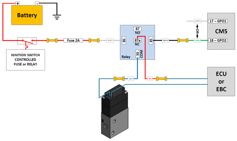
In these cases a different approach can be implemented where a relay is used to break the connection between the EBC (or the Engine Computer) and the boost solenoid. This is accomplished by connecting a relay in-line with one of the boost solenoid wires by using the relay's Normally Closed (NC) and Common (COM) terminals ensuring the boost solenoid and whatever is controlling it are connected by default whenever the relay is OFF. The relay itself is controlled by the appropriate GPO on the CM5/CM5-LT and whener WMI trouble is detected the GPO activates the relay which breaks the flow of current through the boost solenoid and causes it to close. This drops the boost to whatever the wastegate spring is set to with the aim of saving the engine by doing so.

The wiring diagram for this approach is shown here:

Generic Boost Cut Strategy


   CM5/CM5-LT Generic Boost-Cut Wiring Diagram

Posted by Torq Byter_ on 01 January, 2017 Read more →

GPO - Relay Control

CM5 and CM5-LT are equipped with two, pull-to-ground, General Purpose Outputs, GPO1 and GPO2 that can each be configured to switch ON or OFF either ABOVE or BELOW some setpoint.

This setpoint is a combination of engine RPM and either boost or analog voltage inputs A or B.

GPOs are limited to sinking 1.5A or less. In situations where higher current is required a relay must be used. This blog post covers relay control with the CM5/CM5-LT.

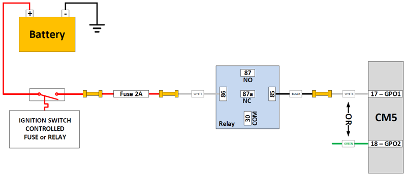
Since the GPOs are pull-to-ground outputs the correct wiring is to connect the relay's positive coil terminal to a switched ignition source that is a part of the vehicle's factory electrical system. This way, the relay's coil will only receive power when the ignition is ON. It's important to install a 2A fuse in-line with this connection and place it as close as possible to the ignition switched source where the power is being taken from.

The relay's negative coil terminal should be connected to the desired GPO on the CM5-LT.

Whenever a GPO on the CM5 activates, the relay will operate and connect (or disconnect) the signals you have attached to its Common (COM), Normally Open (NO) and Normally Closed (NC) terminals.

Torqbyte GPO Relay Control

   CM5/CM5-LT Relay Wiring Diagram

 Testing the Wiring

BEFORE using the relay, the wiring should be checked.

This is easily done using the Output Overrides on the main Settings Tab in TorqTune.

Turn the key to ACCESSORY, but don't start the engine.

Connect a USB cable between the CM5 and your Windows laptop and launch TorqTune. Ensure the unit is connected by looking for a green LED at the bottom right corner of TorqTune.

Once TorqTune shows the unit is connected navigate to the Output Duty Overrides section at the bottom left corner of the Settings tab.

Make sure you are close enough to the relay so you can her its "clicks".

Let's assume your relay is connected to GPO1. Enter 100 in the GPO1 duty field and hit Set. You should hear the relay "click" ON.

Now hit Reset. You should hear the relay "click" OFF.

This should confirm that your wiring is correct. Turn the ignition OFF.

TorqTune Configuration

This section assumes that your MAP sensor is properly calibrated and that all the key parameters on the Settings tab have been entered correctly.

Navigate to the appropriate GPO Table tab and from the Vertical Axis dropdown menu select whether you want to control the relay based on boost (i.e. the MAP sensor) or based on one of the two 0-5V analog inputs A or B.

We'll be using boost in this example.

From the Mode dropdown menu, select either the ON above setpoint, OFF below it mode or the OFF above setpoint, ON below it mode. Do not use the Duty table mode since the relays cannot be driven with a variable duty signal that is generated in this mode.

The other four modes would turn the GPO ON or OFF depending on whether or not there was a soft overcurrent or undercurrent fault detected on the MAIN or AUX pump output, but that is covered in a separate blog post HERE

In the ON above setpoint, OFF below it mode example shown below, the GPO (and the relay) will turn ON whenever the RPM and boost BOTH rise above the entered values (4 PSI and 1500 RPM, in this case). When either RPM or boost drop below their respective value the GPO (and the relay) will turn OFF.

If only RPM or only boost should be used for GPO control in this mode, simply enter zero (0) for the parameter that should be ignored.

In the OFF above setpoint, ON below it mode example shown below, the situation is reversed. The GPO (and the relay) will turn OFF whenever the RPM and boost BOTH rise above the entered values (4 PSI and 1500 RPM, in this case). When either RPM or boost drop below their respective value the GPO (and the relay) will turn ON.

If only RPM or only boost should be used for GPO control in this mode, simply enter maximum value allowable (by ticking the UP arrow as far as it will go) for the parameter that should be ignored.

In some set-ups it may be desirable to control the time delay (in milliseconds) between the instant the setpoint threshold is physically crossed and the instant the GPO (or the relay) turns ON or OFF. These two time periods are called Activation Delay and Deactivation Delay and implement a feature called hysteresis. You should only use this if necessary in your setup. If not required, just keep these values set to zero (0).

Posted by Torq Byter_ on 01 January, 2017 Read more →

GPO - Auxiliary Injector Control

CM5 and CM5-LT are equipped with two, pull-to-ground, General Purpose Outputs, GPO1 and GPO2 that can each be controlled with a separate 3D 16x16 cell duty table. In this mode the outputs are pulsed at a fixed frequency of 30Hz.

One possible use for these outputs is controlling auxiliary injectors that provide supplemental fuelling in direct injected applications.

Each GPO can sink up to 1.5A, which rules using low-impedance injectors since those injectors all draw more than 1.5A.

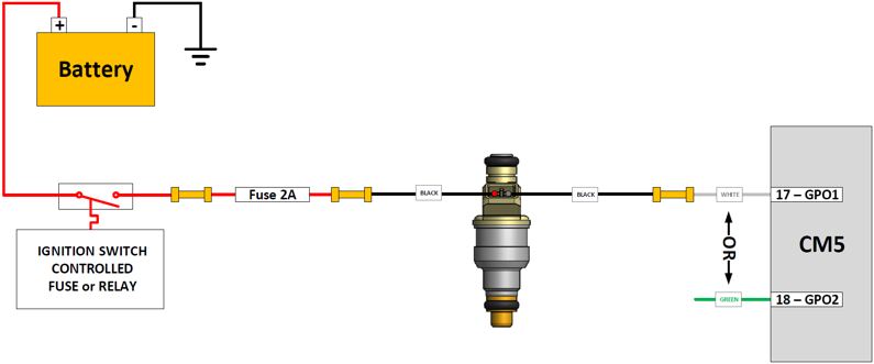
The negative terminal of an auxiliary high-impedance injector is connected to one of the CM5's GPOs. The positive terminal is connected to a relay or fuse that goes HOT whenever the ignition is ON. This would be part of the vehicle's existing electrical system. It is important to set things up so that injector see any power when the engine is off. This enusres the injector doesn't accidentally turn on when the engine is OFF. It is also important to use a 2A fuse in line with the injectors power feed. This fuse must be installed as close to the power source as possible.

Whenever a GPO on the CM5 activates, the injector will open and inject fuel.

GPO Injector Control - Direct

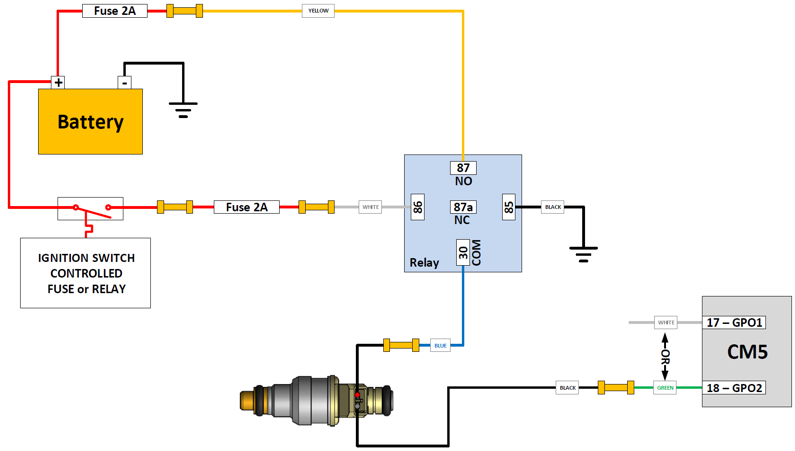
In vehicles where the factory switched ignition circuit doesn't have enough spare capacity to deal with an additional 2A load in the form of the auxiliary injector, a relay must be added and connected as follows:

GPO Injector Control - Relay

Note that the relay requires its own 2A fuse placed right at the battery.

In this set-up the ignition circuit only needs to power the relay coil which is a very light load. With the ignition on, the relay is automatically activated and the battery power from the Normally Open (NO) relay terminal 87 is connected to the Common (COM) terminal 30 supplying power to the injector.

As before, whenever GPO on the CM5 activates and provides a path to ground the injector will open and inject fuel.

   CM5/CM5-LT Injector Wiring Diagram

Testing the Wiring

BEFORE connecting the pressurized fuel line to the injector, the wiring should be checked.

This is easily done using the Output Overrides on the main Settings Tab in TorqTune.

Turn the key to ACCESSORY, but don't start the engine.

Connect a USB cable between the CM5 and your Windows laptop and launch TorqTune. Ensure the unit is connected by looking for a green LED at the bottom right corner of TorqTune.

Once TorqTune shows the unit is connected navigate to the Output Duty Overrides section at the bottom left corner of the Settings tab.

Have a helper, who is wearing safety glasses, near the injector and ask him/her to let you know when the injector "clicks".

Let's assume your injector is connected to GPO1. Enter 100 in the GPO1 duty field and hit Set. The helper should hear the injector "click" ON. Don't run the injector like this for more than a couple of seconds !!!

Now hit Reset. The helper should hear the injector "click" OFF.

This should confirm that your wiring is correct. Turn the ignition OFF.

TorqTune Configuration

This section assumes that your MAP sensor is properly calibrated and that all the key parameters on the Settings tab have been entered correctly.

Navigate to the appropriate GPO Table tab and place that GPO in Duty table mode. DO NOT select any of the other modes since they only switch hard ON (i.e. at 100% duty) which is intended for driving solenoids or relays but not for driving injectors.


Next, set the RPM and Boost values above which the table should be "active". This doesn't mean that the injector will turn on when both of these values are exceeded. It just means that the unit won't even look at the duty table values below these limits. You typically want to set the RPM value to something well above idle and the Boost value somewhere above your wastegate spring pressure.

Here we're using 10 PSI and 1500 RPM ensuring the table isn't even looked at when the boost is below 10 PSI or engine speed is less than 1500 RPM. You should use values here that make sense in your set-up.

Next fill the table with duty cell values that make sense for your set-up. This will depend largely on your tuning, the size of auxiliary injector, your fuel pressure and the fuelling requirements of your set-up. Keep in mind that the CM5-LT's output is not synchronized to the firing events of the main injectors, so don't go too high on the entered duty values especially low in the RPM band.

Here is a sample table from a big turbo TFSI set-up running a 1000cc High Impedance auxiliary injector.


When you are happy with your table hit Write All to apply your calibration to the unit. Don't forget to SaveAs and store your calibration files so you can go back to a previous version if something goes wrong.

Enjoy the extra fuelling.

Posted by Torq Byter_ on 30 December, 2016 Read more →

Using an LED to Show WMI Activity

Many users prefer to install a Light Emitting Diode (LED), somewhere on the dash, in order to show the activity of their Water Methanol Injection (WMI) system.

With the CM5/CM5-LT this can be easily accomplished using two basic approaches.

First some LED theory...

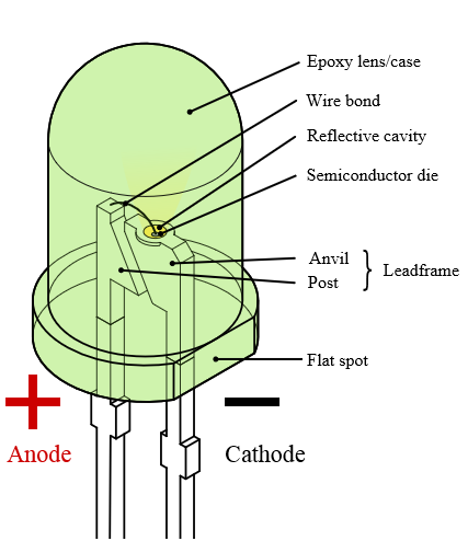
A LED is a two-terminal, polarized device. That means that its polarity must be considered when it's installed or it will not turn on. The two terminals are called CATHODE and ANODE. When the CATHODE is connected to GROUND and the ANODE is connected to a positive voltage, the LED will turn on.

LED Polarity

The CM5/CM5-LT has two General Purpose Outputs (GPO1 and GPO2) which can be used to control an LED. These outputs are "pull-to-ground" type which means that whatever load is connect to a GPO it will be connected to ground whenever that GPO is active.

So the LED's ANODE must be connected to a positive voltage while its CATHODE must be connected to the GPO on the CM5/CM5-LT what will be used to control it.

The positive voltage in the diagram shown above can be either 5Vdc that is taken from one of the spare RED (5Vdc) wires on the CM5/CM5-LT's Input/Output connector, or it can be 12Vdc sourced from a switched and fuse-protected connection somewhere else in the vehicle. LEDs draw very little current (around 0.02A) so they won't likely overload an existing ignition-switched 12Vdc circuit in the car.

Majority of LEDs operate at around 2Vdc. This is called their Forward Voltage. In order to run an LED from 5Vdc or 12Vdc, an in-line (aka series) resistor is required, which will drop the higher voltage to the 2Vdc level the LED can operate at. Connecting an LED directly to 5Vdc or 12Vdc without a series resistor will destroy the LED.

If using a regular LED such as the one described above, the following series resistor is recommended for 5Vdc operation:

and for 12Vdc operation:


There are many LEDs that come with a built-in series resistor that can be safely operated from from 5Vdc or 12Vdc eliminating the need for adding your own resistors shown above.

Here are some examples of LEDs that come with a threaded metal bezel and 6" long lead wires, which greatly simplify dash mounting:

L60D-G5-W (Green 5Vdc)
L60D-G12-W (Green 12Vdc)

L60D-R5-W (Red 5Vdc)
L60D-R12-W (Red 12Vdc)

L60D-A5-W (Yellow 5Vdc)
L60D-A12-W (Yellow 12Vdc)

There are many other colors and bezel styles available.

There are two basic LED indication modes that can be implemented in TorqTune to show WMI activity:

1. Hard ON/OFF LED Operation - The LED is fully ON when the pump is running and fully OFF when the pump is OFF.

2. Pump Duty-Matched LED Operation - The LED is operated with the same duty as the pump. This causes the LED to flash faster (i.e. get brighter) or slower (i.e. get dimmer) depending on the pump's duty.

Assuming the LED is correctly wired to GPO1 and assuming the following table is used for WMI pump control on the CM5/CM5-LT's MAIN output here is how the two approaches can be realized.

1. Hard ON/OFF LED Operation

To have the LED turn ON when the pump starts we need to look at the table entered on the Main Table tab. This will obviously vary from set-up to set-up, but in this example we can see the pump is off at 2500 RPM or less and 6 PSI of boost or less.

The CM5/CM-LT will start the pump as soon as these two values are exceeded, so on the GPO1 settings screen we should:

1. Select the mode ON above setpoint, OFF below it from the GPO1 control dropdown menu.
2. Set value in the MAP sensor is equal to or greater than field to 6.0 PSI.
3. Set value in the Engine Speed is equal to or greater than field to 2500 RPM.

With these settings applied the LED will turn on as soon as the pump duty is non-zero and will stay ON regardless of the actual pump duty.

2. Pump Duty-Matched LED Operation

To have the LED flash faster or slower (i.e. dim and brighten) in relation to actual pump duty, simply enter all the same settings (including the table cell values) on the GPO1 Table tab as were entered on the Main Table.

Main Table:

GPO1 Table:

With these settings applied the GPO1 duty will track that of the Main output and the LED will provide a visual indicator of the relative magnitude of the pump's duty.


Posted by Torq Byter_ on 30 October, 2016 Read more →

Wiring Tutorial: Unit Power and Ground

Torqbyte units are intended for driving heavy electrical loads. This makes proper power and ground wiring absolutely essential. Poor or inadequate wiring can prevent the unit from operating properly (at best) or could cause a fire hazard. If the installer is not familiar with basic electrical theory, lacks the proper assembly tools, or is not familiar with the target vehicle's electric system, the installation should be referred to an experienced professional.

In this post we will look at several options that can be used to provide proper power and ground wiring for your Torqbyte unit(s).

Before we get into all the details, let's first address some Frequently Asked Questions:

Q. Do I need to install a fuse?
A. Yes, you do.

Q. Why?
A. Fuses protect wires from overheating and possibly catching fire, which could happen if a power wire gets shorted to ground with nothing to limit the huge current that will start to flow. Any time you have a power wire running any significant length away from a power source (i.e. the car's battery), you should install a fuse.

Q. Where should I install the fuse?
A. To be effective the fuse MUST be located as close to the battery as possible. Any length of wire between the battery and the fuse is no protected, so it's important to keep this length as short as possible.

Q. What wire is used in your kits?
A. We only use the SXL automotive wire that meets the SAE J1127 standard. The SXL-10 wire we use is a heavy gauge automotive wire that also has an extra thick outer jacket. 

Q. I don't live in the US or Canada. Where can I get this 10AWG (aka 10 Gauge) wire?

A. AWG stands for American Wire Gauge, so the 10AWG wire is generally specific to the North American geographic market. While you may be able to get 10AWG wire in your country, or may be able to order it online and have it shipped to you from a US supplier, we would recommend that you source the functionally equivalent European 6.0mm^2 LEONI Mocar® 125 XE or LEONI Mocar® 180 E automotive wire.

Q. I don't live in the US or Canada. Where can I order these extra bits and pieces?
A. Almost all of the electronic distributors listed above, particularly DigiKey, Mouser and Newark have physical offices and serve customers in many different countries throughout the world. We would recommend sourcing the required material locally to keep your costs down.

Q. Should I crimp or solder?
A. Always crimp. Never solder. Almost every automotive manufacturer prohibits the practice of soldering wires. The primary reason is that soldering can make copper brittle and affect the long-term reliability of the solder joint in a high vibration automotive environment. Crimped joints are mechanical and electrically superior, anyways. Don't solder.

Q. The recommended crimping tools (discussed at the bottom of this post) are quite expensive. I'd like to avoid paying that much money for a one-time use tool. Is there any other way that I can crimp these wire splices and terminals?
A. You are absolutely right that those tools are pretty expensive if you don't think that will use them more then once or twice. As with anything, there is always a different way to do something. Will that other approach produce results that are the same, better or worse than what can be achieved when using the recommended tools and procedures? We don't know. So we can't recommend anything that we haven't tried and that may conflict with the manufacturer's recommendations.

Q. This is all great to know, but I don't have time to read all this and even less time to make my own power wiring. Can you custom-make all the necessary wiring for me and just send me a ready-to-install harness?
A. Absolutely. We have all the materials and manufacturer-recommended tooling in-house and all we need from you is a napkin sketch, a few measurements.

Alright... Let's get started.

We will make a number of references here to Volkswagen and Audi vehicles just to illustrate the relevant topics. However, the concepts described below can be easily extended to a vast majority of modern vehicles.

We will focus our attention on the fuse box in the engine compartment because it is the most convenient location from which to pick up battery power. The reason that fuse box is a good starting place is that it comes with spare wire guides, studs/fasteners and a protective cover which will protect the new wiring and ensure the installation looks clean and neat when everything is put back together. Although this discussion is most applicable to vehicles with a front-mounted battery, the concepts are the same for vehicles with a trunk-mounted battery.

The fuse box in question is shown below:

Power Wiring Front Battery Option A

If you are installing the power wiring on a VAG vehicle that comes with a power distribution module with integrated fuses VW Part No. 1K0 937 829 (A), your job will be relatively simple.

The rightmost 40A fuse on this module is usually not used in the cars that use it. That 40A also happens to be the exact value that we need.

Note: Only use the 40A location !!! Anything with a rating higher than 40A will not protect your 10AWG wiring.

As we can see in the vehicle shown below, the rightmost 40A fuse is not used and the output end of the fuse even has an M5 stud that can receive our power wire.

The first thing you'll need to get is a yellow (10AWG) ring terminal (or ring lug) with a hole that can accept an M5 stud.

Although you can use whatever ring terminal you want we recommend either a TE Part No. B-106-1503 which is a heat-shrinkable and sealed ring terminal from their Dura-Seal product line or TE Part No. 130171 which is an unsealed terminal from their PIDG product line.

The Dura-Seal ring terminal can be purchased from E-Sonic.
The PIDG ring terminal can be purchased from DigiKey or Newark.

It should be noted that the other ring terminals in the fuse box are not sealed so it's up to you if you want to keep everything unsealed like the OEM or opt for a sealed terminal.

Using the recommended crimping tool (discussed at the bottom of this post), crimp the ring lug onto the 10AWG wire that you have previously run from the unit's location out to the fuse box. If you are using sealing ring lug, don't forget to heat shrink the insulation until the internal adhesive flows to form a seal around the wire (more on this at the bottom of this post).

The next thing that's required is an M5 nut. You can use a VW Part No. N 101 181 02  which is a self-locking, shouldered M5 hex nut used on other fuses in the fuse box, or you can use a regular stainless steel M5 hex nut and an M5 split lock-washer (Don't forget the lock-washer).

Your final configuration should something like this:


Power Wiring Front Battery Option B

If that rightmost integrated 40A fuse is unavailable,

or your fuse box doesn't even come with an integrated fuse module

but there is an unused M5 stud available, then you can still achieve the same result described in Option A, except that you will need to provide your own 40A fuse and some hardware to keep everything in place.

The first thing you'll need to get is that 40A fuse.

You can order this fuse from your local VW/Audi dealer under VAG Part No. N 10525501 or you can order it from one of the online electronics distributors using the manufacturer's Part No. 153.5631.5401. This LittelFuse part is available from DigiKey or Mouser.

As with Option A, you will need an M5 nut to secure the fuse to the M5 stud in the fuse box. You can order a VW Part No. N 101 181 02  which is a self-locking, shouldered M5 hex nut used on other fuses in the fuse box, or you can just use a regular stainless steel M5 hex nut and a stainless M5 split lock-washer. (Don't forget the lock-washer unless you are using the VW hex nut).

Again you will need an M5 ring terminal and, as before, we recommend using a TE Part No. B-106-1503 which is a heat-shrinkable and sealed ring terminal from their Dura-Seal product line or a TE Part No. 130171 which is an unsealed terminal from their PIDG product line.

The recommended Dura-Seal ring terminal can be purchased from E-Sonic.
The recommended PIDG ring terminal can be purchased from DigiKey or Newark.

It should be mentioned that other ring terminals in the fuse box are not sealed so it's up to you if you want to keep everything unsealed like OEM or use a sealed terminal.

Using the recommended crimping tool (discussed at the bottom of this post), crimp the ring lug onto the 10AWG wire that you have previously run from the unit's location out to the fuse box. If you are using sealing ring lug, don't forget to heat shrink the insulation until the internal adhesive flows to form a seal around the wire (more on this at the bottom of this post).

Finally, you'll need a nut and bolt to connect your ring lug to the other side of the fuse. You can order a shouldered M5x13.5mm bolt VW Part No. 1K0 919 625 and a second self-locking, shouldered M5 hex nut VW Part No. N 101 181 02 or you can just buy a stainless M5 Hex Bolt (about 14mm long), a matching M5 split locking washer and a matching M5 hex nut.

Your final configuration should something like this:

 When everything is in place, your final set-up should look something like this:


Power Wiring Front Battery Option C

If the vehicle you are working on does not have a fuse box similar to the one described above, the last remaining option is to connect the power wire directly to the battery's +ve terminal. This is the traditional approach used when installing new electrical equipment in a vehicle and, if done properly, it will still produce a very clean and reliable end result.

To start you will need a covered automotive inline fuse holder and a corresponding 40A automotive fuse.

We recommend using a LittelFuse fuse holder Part No. FHJC1001G, which is shown below.


This fuse holder can be purchased from DigiKey or Mouser.

The corresponding 40A fuse that fits inside this fuse holder is LittelFuse Part No. 0895040, which is shown below.

This 40A fuse can be purchased from DigiKey or Mouser.

While one of the free-hanging wires on the fuse holder will be connected to the battery with a ring terminal, the other wire will need to be joined to the positive wire that goes out to the unit. To join the fuse holder's "output" wire to your poitive wire run going to the unit, you will also need a yellow (10AWG) sealed wire splice. You can buy a yellow 10AWG splice from your local VW/Audi dealer under VAG Part No. 000 979 943 , but you will have to confirm with them what crimping tool you should be using, because we don't know who makes the splice VW sells nor what is their recommended crimping tool. On the other hand, you can get a slightly better quality yellow 10AWG wire splice from your local General Motors dealer under GM Part No. 19168448, which can be used with the same ratcheting crimping tool as the Dura-Seal splices and contacts described at the bottom of this post. If you'd rather not buy parts from a dealer, we recommend using a TE Part No. D-406-0003, which is a heat-shrinkable and sealed wire splice from TE's Dura-Seal product line.

This Dura-Seal wire splice can be purchased from DigiKey or Mouser.

The last item that you will need is a ring terminal with an opening that can accommodate the diameter of the bolt on your battery's positive terminal.

As with the other two options, we recommend either a sealed ring terminal from TE's Dura-Seal product line or an unsealed terminal from their PIDG product line.

All the 10AWG-compatible ring terminals from TE's sealed Dura-Seal product line are shown below:

All the 10AWG-compatible ring terminals from TE's unsealed PIDG product line are shown below:

Once you have selected a ring terminal part number from the above tables that works with the hardware on your battery's +ve terminal, one of the quickest ways to check where you can buy it, is to enter its part number in the Octopart Search Engine which will show you the current stock of that part at nearly every electronics distributor.

Your final configuration should look something like this:


You should cover the new power wire with some sort of a protective polyester braid or wire loom. Obviously you should not run this wire near any sources of high heat nor any moving parts that may wear through the insulation over time. Also, any time a wire is passed through a piece of metal (like your firewall) it should go through a grommet or a cord grip protect the wire's insulation from getting cut by the sharp edges of the opening that it's passing through.


Power Wiring Rear Battery

If the vehicle you are working on has a trunk-mounted battery, such as a 2011 Audi A4, the +ve battery terminal assembly attachment may already have a location for a spare fuse that you can use.

The first thing you'll need to get is that 40A fuse.

You can order this fuse from your local VW/Audi dealer under VAG Part No. N 10424902 or you can order it from one of the online electronics distributors using the fuse manufacturer's Part No. 156.5677.5401. This LittelFuse part is available from Mouser.

You will need an M6 ring terminal and, as before, we recommend using a TE Part No. B-106-1603 which is a heat-shrinkable and sealed ring terminal from their Dura-Seal product line or a TE Part No. 320569 which is an unsealed terminal from their PIDG product line.

The recommended Dura-Seal ring terminal can be purchased from E-Sonic.
The recommended PIDG ring terminal can be purchased from DigiKey or Newark.

Finally, you'll need two M6 nuts to bolt down the fuse and the ring terminal to the two M6 studs on the battery's +ve terminal block. You can order a flanged self-locking M6 hex nut VW Part No. N 904 880 05.

Alternately you can just buy a stainless steel M6 Hex nut and a matching M6 split locking washer (don't forget the split locking washer if you are using regular "hardware store" M6 nuts).

Your final configuration should something like this:


Ground Wiring

At this point, you should have a pretty good idea about the best way to bring fused power to your Torqbyte unit. The next thing we will focus on is grounding.

The ground connection should not be routed all the way to the battery's -ve terminal, unless the unit is physically very close to the battery, as it might be in the case of a trunk-mounted PM3 in a vehicle (like and Audi A3) that has a trunk-mounted battery.

The ground connection should be as short as possible and just like the +ve power connection the ground connection should be made using 10AWG wire. Obviously do your best to color code the wires based on their function. Use RED wire for power and BLACK wire for ground. This is a good practice and will make your (or someone else's) life easire of you ever have to troubleshoot this wiring in the future.

A technical service wiring diagram for most vehicles shows the factory grounding points throughout the vehicle. You should try to use one of those grounding points unless they are not very accessible or unless you are very confident that you have found another ground connection point that is going to work (i.e. it makes a good electrical contact with the car's chassis).

Here are some examples of potential chassis grounding points in a couple of VAG vehicles.

In a 2012 VW Golf GTI, one of these two points can be used. There are other suitable grounding points that are not shown here.

In a 2012 Audi A3, one of these points can be used. As before, there are other suitable grounding points that are not shown here.

In a 2011 Audi A4, any one of these three grounding points in the spare wheel well can be used for grounding.

Once a grounding point is selected, it's important to measure the diameter of the protruding stud or the grounding bolt and select a proper ring terminal from one of the two tables shown above. Typically Volkswagen uses M8 studs for grounding points in which case you should use.

Although you can use whatever ring terminal you want, we recommend either a TE Part No. B-106-1803 which is a heat-shrinkable and sealed ring terminal from their Dura-Seal product line or TE Part No. 2-35111-1 which is an unsealed terminal from their PIDG product line.

The Dura-Seal ring terminal can be purchased from E-Sonic.
The PIDG ring terminal can be purchased from DigiKey or Newark

With the right ring terminal on hand, the next thing that is required is to prep the mounting location to receive your ground wire ring terminal. While some of these grounding points will be clean, paint -free and otherwise good-to-go, you may select a grounding location which may be oily, dirty or might be painted. Since both the PM3 and the CM5/CM5-LT return a lot of current into the chassis ground, a very good electrical connection is a MUST. Shown below are a few notes on how to prep a painted stud located in the trunk of a 2012 VW Golf GTI.

If the chosen grounding location requires extra hardware (a nut and a split locking washer) you will need to get those as well in order to complete your installation. Once all the pieces are on hand, your final configuration should look like this:

Crimping Tools and Assembly Notes

PIDG Product Line (Unsealed)

The recommended ratcheting hand crimper for PIDG wire terminals is the TE Pro-Crimper III Part No. 58433-3.

Pro-Crimper III for PIDG terminals can be purchased from DigiKey.

Wires that will be crimped into a PIDG ring terminal need to have a strip length of 8.3cm (0.328").

Some manufacturer's notes on the assembly of PIDG terminals are shown below.


Dura-Seal Product Line (Sealed)

The recommended ratcheting crimper for Dura-Seal wire splices and Dura-Seal ring terminals is TE Part No. AD-1522. It's worth mentioning that the General Motors Tool No. J-38125-8 (or GM Part No. 12085115) is interchangeable with AD-1522.

AD-1522  for Dura-Seal terminals can be purchased from Mouser.

Wires that will be crimped into a Dura-Seal wire splice need to to have a strip length of 8.5mm (0.335").
Wires that will be crimped into a Dura-Seal terminal need to have a strip length of 7.0mm (0.275").

Some manufacturer's notes on the assembly of Dura-Seal splices and terminals are shown below.

Posted by Torq Byter_ on 10 November, 2015 Read more →

TorqTune Video Tutorial: Table Editing

Posted by Torq Byter_ on 05 November, 2015 Read more →

Torqbyte CM5 Water Methanol Safety Features

Torqbyte CM5 and Torqbyte CM5-LT can be configured in many different ways to provide a safety mechanism for almost any water methanol injection set-up.

The most dangerous situation in a water methanol injection (WMI) system is the one where the water meth delivery cuts out under high boost. Over the years, many approaches have been attempted to detect and react to system faults. These approaches included using in-tank float level sensors, measuring pump current to estimate the fluid flow rate, and using in-line flow sensors.

However, unless the WMI controller is sophisticated enough to have an output that can be used to trigger a dump of the excess boost pressure whenever a WMI fault is detected, all that a crude WMI controller could do is alert the driver through some kind of a visual (e.g. LED) or audible (e.g. buzzer) indicator, so that he/she can let off the gas and hope the ECU is able to take the necessary steps to save the engine from detonation damage.

CM5 can be configured to detect system faults using any of the above-mentioned approaches and it also has two General Purpose Outputs (GPOs) that can be used to signal a fault condition to the ECU or to an Electronic Boost Controller (EBC) so the excess boost can get dropped to the wastegate spring level. The CM5 can itself be used as a PID-based EBC. In this case, its ability to drop the boost to safe levels is even more straightforward because it is in control of the boost solenoid and can dump all excess boost directly whenever a WMI fault is detected.

In this blog we will look at three safety approaches that CM5 supports to detect and prevent WMI-related system problems.

Safety Approach 1: Pump Current Monitoring

One of the features that sets CM5 apart from other typical WMI controllers is the user-configurable pump current monitoring. Unlike some of the other WMI controllers that attempt to do the impossible and find a relationship between the water meth flow rate and the pump current, the CM5 only looks at the pump current to address the following conditions:

Condition 1: Is the pump drawing more current than it should be? If it is, this could mean that the line between the pump and the nozzle is blocked, or that an anti-siphon solenoid is stuck in the closed position, or that the pump is seized or corroded by moisture and road salt in set-ups where the pump is exposed to the elements. A condition when the pump is drawing more current than expected is called an overcurrent fault.

Condition 2: Is the pump drawing less current than it should be? If it is, this could mean that the pump has run out of fluid because the tank is empty or the line between the tank and the pump is blocked. It could also indicate that the line between the pump and the nozzle has popped off and fluid is being spilled. A condition when the pump is drawing less current than expected is called an undercurrent fault.

A pump that is pushing fluid through a typical WMI system will draw current that should always fall between some nominal low level, shown as (B) below, and some nominal high current level, shown as (A) below, while the system is functioning as expected. One of the parameters that directly affects the pump current is duty. Clearly when the pump duty is 0% the current will also be 0 A, so there is no point checking for an undercurrent condition when the duty is too low. This duty figure, below which there is little use checking the pump current is shown as (C) below. This value depends on the pump model, diameter of the water meth lines, nozzle, etc. Each of these three points must be determined experimentally for each user's given set-up.


One way to experimentally determine these three numbers is by using the Live View and Output Duty Overrides features of the TorqTune software. By using these tools, the user can command the pump to a certain duty and watch the pump current in the live view to see how that value changes when the pump is full, empty, running through a nozzle, pumping into a blocked line, etc. Clearly you should take steps to avoid any engine damage (like hydrolocking) when performing these tests.

Once the (A), (B) and (C) values for the Main Output Limits or for the AUX Output Limits are known they can be entered into TorqTune via the Settings tab as shown below.

The Time delay field controls how much time between a fault being detected and action being taken will be allowed. Each 100 "loops" to about 4 milliseconds (i.e. 0.004 seconds).
Generally for signalling a fault to an ECU or an external EBC a value of either 0% (OFF) or 100% (ON) should be used to override one of the two low power General Purpose Outputs (GPOs) located at I/O Connector Pin 17 (GPO1) or Pin 18 (GPO2).

Using TorqTune, the CM5 can be configured to set the duty of one of its GPOs in reaction to an overcurrent or undercurrent output fault. This is done via the drop down menus on GPO1 and GPO2 control tabs. In this example let's assume that we want GPO1 to turn on or go to 100% duty (i.e. pull its output to ground) whenever an overcurrent or undercurrent fault is detected on the Main output. To do this we would go to the GPO1 Control tab and select ON when MAIN faulted, OFF otherwise from the GPO1 control drop down menu.


Now whenever an overcurrent or undercurrent fault was detected on the Main output, GPO1 will turn ON (i.e. go to 100% duty) and trigger the ECU or an external EBC to react. 

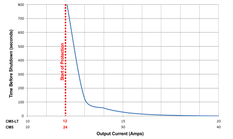
Although it doesn't have anything to do Water Methanol Injection safety, it's worthwhile mentioning what happens in the Hard Current Limit Zone shown in RED above. CM5's high power outputs are rated for 20A each while CM5-LT's outputs are rated for 10A each. Operating the unit with pumps that exceed these current ratings will eventually cause the unit to shut down the overloaded output. How fast or how slow the overloaded output gets shut down will depend on the unit model (i.e. CM5 vs. CM5-LT) and the amount by which the current limit is being exceeded. The graph below shows an approximate relationship between the amount of overloading and the amount of time, in seconds, it will take for the unit to shut down an overloaded output.

Clearly it is undesirable to have either the WMI pump or the fuel pump shut down unexpectedly during regular operation, but this is the only way the unit can protect itself from eventual destruction by an unchecked overload condition. If the unit continued to operate unprotected during an overload, the pump will shut off anyways once the unit is destroyed by the overload condition. So, it is crucial for the user to ensure the pump(s) used will not overload the unit. If more current is required than the CM5-LT or CM5 are able to supply directly, the user could consider slaving a Torqbyte PM3 to the output(s) that requires more current. A Torqbyte PM3 Pump Amplifier can output up to 36A of current. If your set-up requires more than 36A for your fuel or your Water Methanol Pump it's probably worth taking another look at your set-up and seeing if the current approach is really the most optimal.

Safety Approach 2: Fluid Level Monitoring

The most common way to detect WMI trouble is to monitor a float switch that opens or closes based on the level of the fluid in the water meth reservoir. A smart placement of this switch will see it installed so that it reacts not when the the reservoir it totally empty to a point where the pump is starved of fluid, but slightly above that so a low fluid level condition will be flagged while there is still some fluid in the reservoir.

Since the output of a float level switch is essentially a logic signal (i.e. ON or OFF) it can be connected to one of the CM5's General Purpose Inputs (GPIs) located at I/O Connector Pin 7 (GPI1) or Pin 8 (GPI2) as shown:

Then, using TorqTune, the CM5 can be configured to set the duty of one of its outputs to some user entered value. Generally for signalling a fault to an ECU or an external EBC a value of either 0% (OFF) or 100% (ON) should be used to override one of the two low power General Purpose Outputs (GPOs) located at I/O Connector Pin 17 (GPO1) or Pin 18 (GPO2).

In TorqTune this is done via the Settings Tab. In this example let's assume that we want GPO1 to turn on or go to 100% duty (i.e. pull its output to ground) whenever GPI1 is active (i.e. when its being pulled to ground by the float switch). To do this we would focus on the GPI duty table overrides section. First we would select Override GPO1 when high from the GPI1 control drop down menu. Then we would set the Override duty value to 100%.

Now whenever the fluid level in the reservoir is running low and the level switch closes to pull the GPI1 line to ground, GPO1 will turn ON (i.e. go to 100% duty) and trigger the ECU or an external EBC to react. 

Safety Approach 3: Fluid Flow Monitoring

Another way to detect WMI trouble is to use one or two flow sensors which sit in-line between the pump and the engine and/or the pump and the reservoir and generate a 0-5V voltage depending on the flow rate through the sensor.

Since the output of a flow sensor is a voltage ranging from 0-5V it can be connected to one of the CM5's Analog Voltage Inputs located at I/O Connector Pin 13 (AN_A) or Pin 15 (AN_B) as shown:

Then, using TorqTune, the CM5 can be configured to set the duty of one of its outputs to some user entered value. Generally for signalling a fault to an ECU or an external EBC a value of either 0% (OFF) or 100% (ON) should be used to override one of the two low power General Purpose Outputs (GPOs) located at I/O Connector Pin 17 (GPO1) or Pin 18 (GPO2).

In TorqTune this is done via the Settings Tab and the Output tab of the desired GPO. In this example let's assume that we want GPO1 to turn on or go to 100% duty (i.e. pull its output to ground) whenever AN_A drops say 2.5V voltage (assuming that given our flow sensor an output of 2.5V or less represents an unacceptably low water meth flow rate).

To do this we would first focus on the Basic Config section on the Settings tab. First we would set the voltage range limits for the Analog A input. In this example let's set them to 0V (Min) and 5V (Max). 

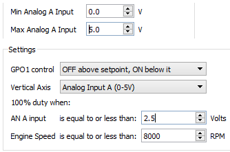
Then on the GPO1 Table tab we would set the GPO1 control drop down menu selection to OFF above setpoint, ON below it. We would also set the Vertical Axis drop down menu selection to Analog Input A. Finally we would define the set point values. Since we don't want the engine RPM to be ever be be a factor we would simply enter the maximum RPM value in the Engine Speed field. In this example we are using 8000 RPM, which is the same value we used for the Maximum Engine Speed on the Settings tab. We would set the AN A input field to the flow rate sensor output voltage that corresponds to some unacceptably low flow rate. We are using 2.5V in this example, but that value depends entirely on the flow rate sensor you are using.


With these settings flashed to the unit, GPO1 would be OFF (i.e. 0%) whenever the AN A voltage was above 2.5V and would be ON (i.e. 100%) whenever the AN A voltage dropped below 2.5V. As before, GPO1 turning ON (i.e. going to 100%) can be used and trigger the ECU or an external EBC to react accordingly.

Any one of these features can be used individually or two and three can be used at the same time allowing the user to achieve whatever desired level of safety for their Water Methanol Injection set-up.  

Posted by Torq Byter_ on 18 October, 2015 Read more →

Connect With Us

Latest Posts

  • Updating CM5-LTS Firmware for Use With TorqTune2

    This guide will explain how to update the CM5-LTS firmware so the unit can be used with the latest TorqTune2 software. Note: This firmware update can only be performed on current CM5-LTS units with rectangular LEDs. It is not compatible with... Read more →

  • Determining TorqTune2 MAP Sensor Values

    CM5-LTS is able to obtain boost readings from any analog 0-5V Manifold Absolute Pressure (MAP) sensor, but it requires the user to provide a few senor-specific MAP Calibration parameters (Slope, Intercept, Atmosphere and Deadband) in order to accurately convert the... Read more →

  • Using the Factory BMW T/MAP Sensors with the CM5-LTS

    In most BMW applications with a CM5-LTS WMI controller, it is preferred to obtain boost readings by "teeing" into the factory TMAP sensor wiring. Below is the information on how to do this for several popular BMW TMAPs we have... Read more →