
GPO - Auxiliary Injector Control
CM5 and CM5-LT are equipped with two, pull-to-ground, General Purpose Outputs, GPO1 and GPO2 that can each be controlled with a separate 3D 16x16 cell duty table. In this mode the outputs are pulsed at a fixed frequency of 30Hz.
One possible use for these outputs is controlling auxiliary injectors that provide supplemental fuelling in direct injected applications.
Each GPO can sink up to 1.5A, which rules using low-impedance injectors since those injectors all draw more than 1.5A.
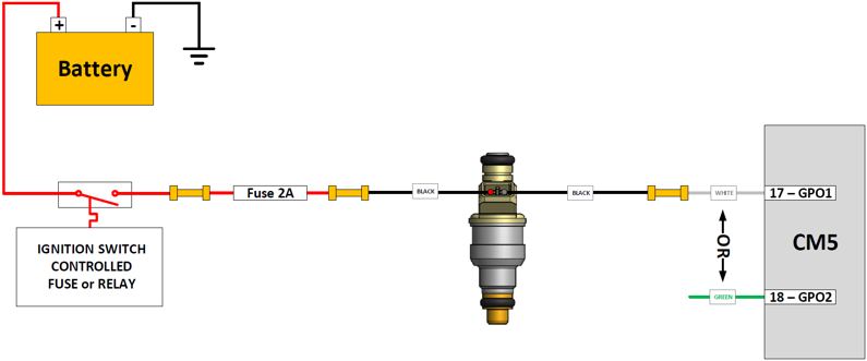
The negative terminal of an auxiliary high-impedance injector is connected to one of the CM5's GPOs. The positive terminal is connected to a relay or fuse that goes HOT whenever the ignition is ON. This would be part of the vehicle's existing electrical system. It is important to set things up so that injector see any power when the engine is off. This enusres the injector doesn't accidentally turn on when the engine is OFF. It is also important to use a 2A fuse in line with the injectors power feed. This fuse must be installed as close to the power source as possible.
Whenever a GPO on the CM5 activates, the injector will open and inject fuel.
In vehicles where the factory switched ignition circuit doesn't have enough spare capacity to deal with an additional 2A load in the form of the auxiliary injector, a relay must be added and connected as follows:
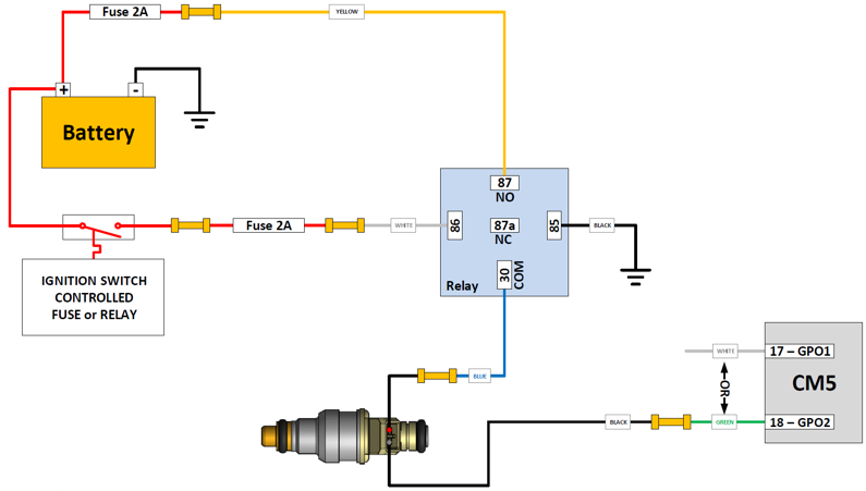
Note that the relay requires its own 2A fuse placed right at the battery.
In this set-up the ignition circuit only needs to power the relay coil which is a very light load. With the ignition on, the relay is automatically activated and the battery power from the Normally Open (NO) relay terminal 87 is connected to the Common (COM) terminal 30 supplying power to the injector.
As before, whenever GPO on the CM5 activates and provides a path to ground the injector will open and inject fuel.
![]() CM5/CM5-LT Injector Wiring Diagram
CM5/CM5-LT Injector Wiring Diagram
Testing the Wiring
BEFORE connecting the pressurized fuel line to the injector, the wiring should be checked.
This is easily done using the Output Overrides on the main Settings Tab in TorqTune.
Turn the key to ACCESSORY, but don't start the engine.
Connect a USB cable between the CM5 and your Windows laptop and launch TorqTune. Ensure the unit is connected by looking for a green LED at the bottom right corner of TorqTune.
Once TorqTune shows the unit is connected navigate to the Output Duty Overrides section at the bottom left corner of the Settings tab.

Have a helper, who is wearing safety glasses, near the injector and ask him/her to let you know when the injector "clicks".
Let's assume your injector is connected to GPO1. Enter 100 in the GPO1 duty field and hit Set. The helper should hear the injector "click" ON. Don't run the injector like this for more than a couple of seconds !!!

Now hit Reset. The helper should hear the injector "click" OFF.

This should confirm that your wiring is correct. Turn the ignition OFF.
TorqTune Configuration
This section assumes that your MAP sensor is properly calibrated and that all the key parameters on the Settings tab have been entered correctly.
Navigate to the appropriate GPO Table tab and place that GPO in Duty table mode. DO NOT select any of the other modes since they only switch hard ON (i.e. at 100% duty) which is intended for driving solenoids or relays but not for driving injectors.

Next, set the RPM and Boost values above which the table should be "active". This doesn't mean that the injector will turn on when both of these values are exceeded. It just means that the unit won't even look at the duty table values below these limits. You typically want to set the RPM value to something well above idle and the Boost value somewhere above your wastegate spring pressure.

Here we're using 10 PSI and 1500 RPM ensuring the table isn't even looked at when the boost is below 10 PSI or engine speed is less than 1500 RPM. You should use values here that make sense in your set-up.
Next fill the table with duty cell values that make sense for your set-up. This will depend largely on your tuning, the size of auxiliary injector, your fuel pressure and the fuelling requirements of your set-up. Keep in mind that the CM5-LT's output is not synchronized to the firing events of the main injectors, so don't go too high on the entered duty values especially low in the RPM band.
Here is a sample table from a big turbo TFSI set-up running a 1000cc High Impedance auxiliary injector.


When you are happy with your table hit Write All to apply your calibration to the unit. Don't forget to SaveAs and store your calibration files so you can go back to a previous version if something goes wrong.
Enjoy the extra fuelling.