
Torqbyte CM5 Water Methanol Safety Features
Torqbyte CM5 and Torqbyte CM5-LT can be configured in many different ways to provide a safety mechanism for almost any water methanol injection set-up.
The most dangerous situation in a water methanol injection (WMI) system is the one where the water meth delivery cuts out under high boost. Over the years, many approaches have been attempted to detect and react to system faults. These approaches included using in-tank float level sensors, measuring pump current to estimate the fluid flow rate, and using in-line flow sensors.
However, unless the WMI controller is sophisticated enough to have an output that can be used to trigger a dump of the excess boost pressure whenever a WMI fault is detected, all that a crude WMI controller could do is alert the driver through some kind of a visual (e.g. LED) or audible (e.g. buzzer) indicator, so that he/she can let off the gas and hope the ECU is able to take the necessary steps to save the engine from detonation damage.
CM5 can be configured to detect system faults using any of the above-mentioned approaches and it also has two General Purpose Outputs (GPOs) that can be used to signal a fault condition to the ECU or to an Electronic Boost Controller (EBC) so the excess boost can get dropped to the wastegate spring level. The CM5 can itself be used as a PID-based EBC. In this case, its ability to drop the boost to safe levels is even more straightforward because it is in control of the boost solenoid and can dump all excess boost directly whenever a WMI fault is detected.
In this blog we will look at three safety approaches that CM5 supports to detect and prevent WMI-related system problems.
Safety Approach 1: Pump Current Monitoring
One of the features that sets CM5 apart from other typical WMI controllers is the user-configurable pump current monitoring. Unlike some of the other WMI controllers that attempt to do the impossible and find a relationship between the water meth flow rate and the pump current, the CM5 only looks at the pump current to address the following conditions:
Condition 1: Is the pump drawing more current than it should be? If it is, this could mean that the line between the pump and the nozzle is blocked, or that an anti-siphon solenoid is stuck in the closed position, or that the pump is seized or corroded by moisture and road salt in set-ups where the pump is exposed to the elements. A condition when the pump is drawing more current than expected is called an overcurrent fault.
Condition 2: Is the pump drawing less current than it should be? If it is, this could mean that the pump has run out of fluid because the tank is empty or the line between the tank and the pump is blocked. It could also indicate that the line between the pump and the nozzle has popped off and fluid is being spilled. A condition when the pump is drawing less current than expected is called an undercurrent fault.
A pump that is pushing fluid through a typical WMI system will draw current that should always fall between some nominal low level, shown as (B) below, and some nominal high current level, shown as (A) below, while the system is functioning as expected. One of the parameters that directly affects the pump current is duty. Clearly when the pump duty is 0% the current will also be 0 A, so there is no point checking for an undercurrent condition when the duty is too low. This duty figure, below which there is little use checking the pump current is shown as (C) below. This value depends on the pump model, diameter of the water meth lines, nozzle, etc. Each of these three points must be determined experimentally for each user's given set-up.

One way to experimentally determine these three numbers is by using the Live View and Output Duty Overrides features of the TorqTune software. By using these tools, the user can command the pump to a certain duty and watch the pump current in the live view to see how that value changes when the pump is full, empty, running through a nozzle, pumping into a blocked line, etc. Clearly you should take steps to avoid any engine damage (like hydrolocking) when performing these tests.
Once the (A), (B) and (C) values for the Main Output Limits or for the AUX Output Limits are known they can be entered into TorqTune via the Settings tab as shown below.

The Time delay field controls how much time between a fault being detected and action being taken will be allowed. Each 100 "loops" to about 4 milliseconds (i.e. 0.004 seconds).
Generally for signalling a fault to an ECU or an external EBC a value of either 0% (OFF) or 100% (ON) should be used to override one of the two low power General Purpose Outputs (GPOs) located at I/O Connector Pin 17 (GPO1) or Pin 18 (GPO2).
Using TorqTune, the CM5 can be configured to set the duty of one of its GPOs in reaction to an overcurrent or undercurrent output fault. This is done via the drop down menus on GPO1 and GPO2 control tabs. In this example let's assume that we want GPO1 to turn on or go to 100% duty (i.e. pull its output to ground) whenever an overcurrent or undercurrent fault is detected on the Main output. To do this we would go to the GPO1 Control tab and select ON when MAIN faulted, OFF otherwise from the GPO1 control drop down menu.
Now whenever an overcurrent or undercurrent fault was detected on the Main output, GPO1 will turn ON (i.e. go to 100% duty) and trigger the ECU or an external EBC to react.
Although it doesn't have anything to do Water Methanol Injection safety, it's worthwhile mentioning what happens in the Hard Current Limit Zone shown in RED above. CM5's high power outputs are rated for 20A each while CM5-LT's outputs are rated for 10A each. Operating the unit with pumps that exceed these current ratings will eventually cause the unit to shut down the overloaded output. How fast or how slow the overloaded output gets shut down will depend on the unit model (i.e. CM5 vs. CM5-LT) and the amount by which the current limit is being exceeded. The graph below shows an approximate relationship between the amount of overloading and the amount of time, in seconds, it will take for the unit to shut down an overloaded output.
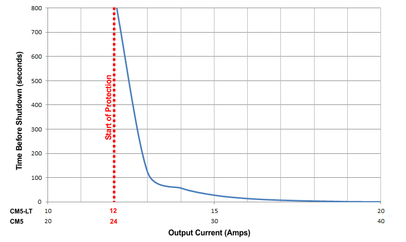
Clearly it is undesirable to have either the WMI pump or the fuel pump shut down unexpectedly during regular operation, but this is the only way the unit can protect itself from eventual destruction by an unchecked overload condition. If the unit continued to operate unprotected during an overload, the pump will shut off anyways once the unit is destroyed by the overload condition. So, it is crucial for the user to ensure the pump(s) used will not overload the unit. If more current is required than the CM5-LT or CM5 are able to supply directly, the user could consider slaving a Torqbyte PM3 to the output(s) that requires more current. A Torqbyte PM3 Pump Amplifier can output up to 36A of current. If your set-up requires more than 36A for your fuel or your Water Methanol Pump it's probably worth taking another look at your set-up and seeing if the current approach is really the most optimal.
Safety Approach 2: Fluid Level Monitoring
The most common way to detect WMI trouble is to monitor a float switch that opens or closes based on the level of the fluid in the water meth reservoir. A smart placement of this switch will see it installed so that it reacts not when the the reservoir it totally empty to a point where the pump is starved of fluid, but slightly above that so a low fluid level condition will be flagged while there is still some fluid in the reservoir.
Since the output of a float level switch is essentially a logic signal (i.e. ON or OFF) it can be connected to one of the CM5's General Purpose Inputs (GPIs) located at I/O Connector Pin 7 (GPI1) or Pin 8 (GPI2) as shown:

Then, using TorqTune, the CM5 can be configured to set the duty of one of its outputs to some user entered value. Generally for signalling a fault to an ECU or an external EBC a value of either 0% (OFF) or 100% (ON) should be used to override one of the two low power General Purpose Outputs (GPOs) located at I/O Connector Pin 17 (GPO1) or Pin 18 (GPO2).
In TorqTune this is done via the Settings Tab. In this example let's assume that we want GPO1 to turn on or go to 100% duty (i.e. pull its output to ground) whenever GPI1 is active (i.e. when its being pulled to ground by the float switch). To do this we would focus on the GPI duty table overrides section. First we would select Override GPO1 when high from the GPI1 control drop down menu. Then we would set the Override duty value to 100%.

Now whenever the fluid level in the reservoir is running low and the level switch closes to pull the GPI1 line to ground, GPO1 will turn ON (i.e. go to 100% duty) and trigger the ECU or an external EBC to react.
Safety Approach 3: Fluid Flow Monitoring
Another way to detect WMI trouble is to use one or two flow sensors which sit in-line between the pump and the engine and/or the pump and the reservoir and generate a 0-5V voltage depending on the flow rate through the sensor.
Since the output of a flow sensor is a voltage ranging from 0-5V it can be connected to one of the CM5's Analog Voltage Inputs located at I/O Connector Pin 13 (AN_A) or Pin 15 (AN_B) as shown:

Then, using TorqTune, the CM5 can be configured to set the duty of one of its outputs to some user entered value. Generally for signalling a fault to an ECU or an external EBC a value of either 0% (OFF) or 100% (ON) should be used to override one of the two low power General Purpose Outputs (GPOs) located at I/O Connector Pin 17 (GPO1) or Pin 18 (GPO2).
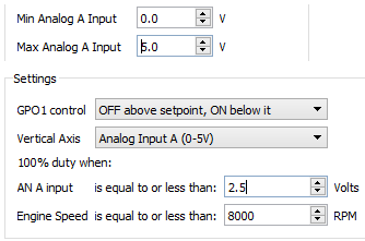
In TorqTune this is done via the Settings Tab and the Output tab of the desired GPO. In this example let's assume that we want GPO1 to turn on or go to 100% duty (i.e. pull its output to ground) whenever AN_A drops say 2.5V voltage (assuming that given our flow sensor an output of 2.5V or less represents an unacceptably low water meth flow rate).
To do this we would first focus on the Basic Config section on the Settings tab. First we would set the voltage range limits for the Analog A input. In this example let's set them to 0V (Min) and 5V (Max).
Then on the GPO1 Table tab we would set the GPO1 control drop down menu selection to OFF above setpoint, ON below it. We would also set the Vertical Axis drop down menu selection to Analog Input A. Finally we would define the set point values. Since we don't want the engine RPM to be ever be be a factor we would simply enter the maximum RPM value in the Engine Speed field. In this example we are using 8000 RPM, which is the same value we used for the Maximum Engine Speed on the Settings tab. We would set the AN A input field to the flow rate sensor output voltage that corresponds to some unacceptably low flow rate. We are using 2.5V in this example, but that value depends entirely on the flow rate sensor you are using.
With these settings flashed to the unit, GPO1 would be OFF (i.e. 0%) whenever the AN A voltage was above 2.5V and would be ON (i.e. 100%) whenever the AN A voltage dropped below 2.5V. As before, GPO1 turning ON (i.e. going to 100%) can be used and trigger the ECU or an external EBC to react accordingly.
Any one of these features can be used individually or two and three can be used at the same time allowing the user to achieve whatever desired level of safety for their Water Methanol Injection set-up.